The ZF 6HP26 Transmission is found in a wide range of vehicles from the early 2000’s through the mid 2010’s. Manufacturers such as Audi, BMW, Jaguar, and even Maserati have adopted the use of this 6 speed automatic gearbox. The 6HP26 is capable of handling a high torque demand and is generally a reliable transmission when maintained properly.
Some vehicle manufacturers specify that the transmission has a lifetime fill, but unfortunately, this is not the case. The 6HP26 should be serviced at intervals of 50,000 to 60,000 miles using only the specific ZF fluid. A common issue is external leakage from the plastic oil pan and Mechatronic connector sleeve. Since the filter is integrated with the oil pan, it should be replaced anyway when servicing the unit. This article demonstrates servicing the transmission in a 2008 Range Rover with around 60,000 miles.
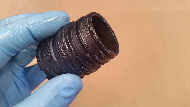
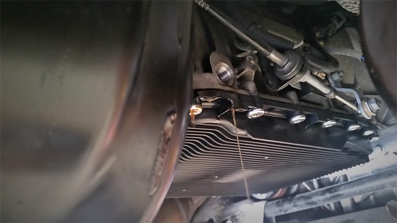
The oil pan and Mechatronics connector sleeve are beginning to show evidence of oil seepage.
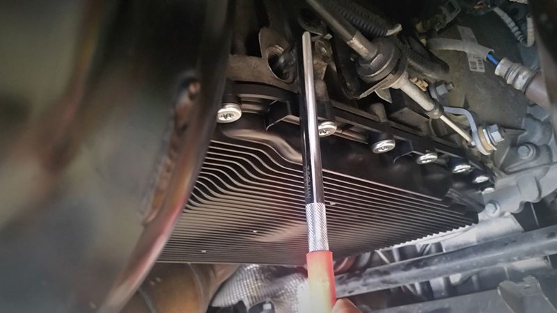
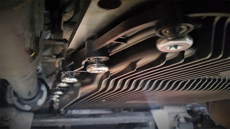
Locate the drain plug, and loosen it using a 10 mm hex bit. Then remove the oil pan bolts with a T40 torx bit.

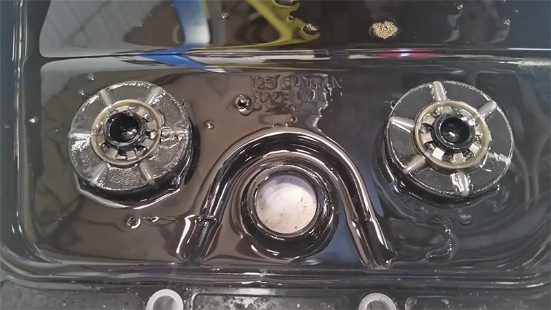
Inspect the magnets for any abnormal metal fragments. The magnets will have some attracted amount of friction material. The magnets shown here indicate normal wear.
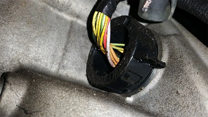
Disconnect the Mechatronic electrical connector by rotating the connector locking ring counterclockwise. Position the connector out of the way to access the connector sleeve.

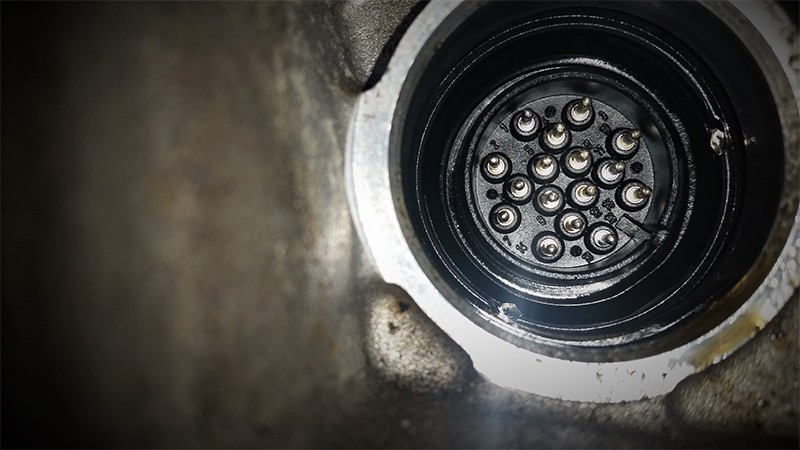
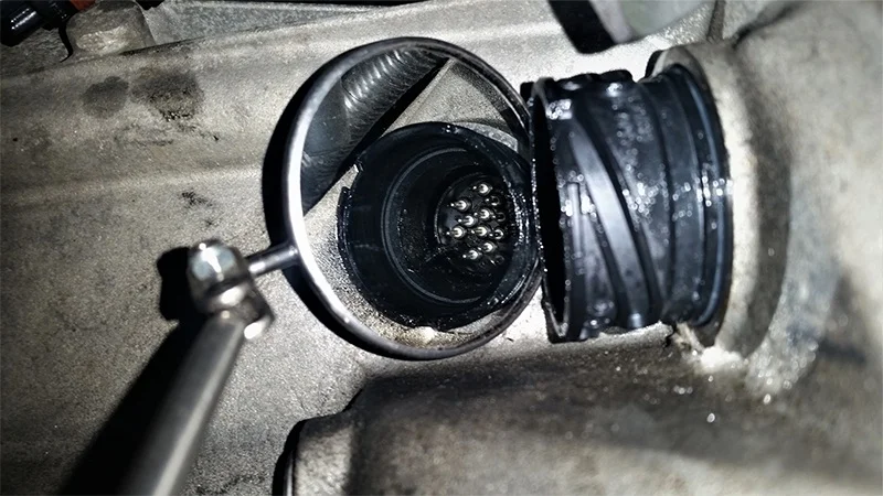
The white locking mechanism secures the connector sleeve in its housing. Press the tab on the locking mechanism and pull downward, wiggling it slightly. Do not force anything! If this tab breaks, the Mechatronic assembly will need to be replaced.
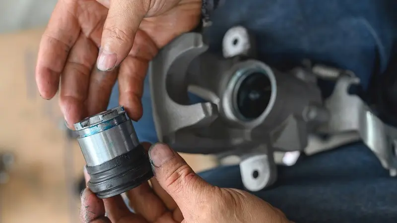
Remove the Mechatronic connector sleeve. It should come out easily. You may need to pry it gently with a screwdriver in order to remove it.
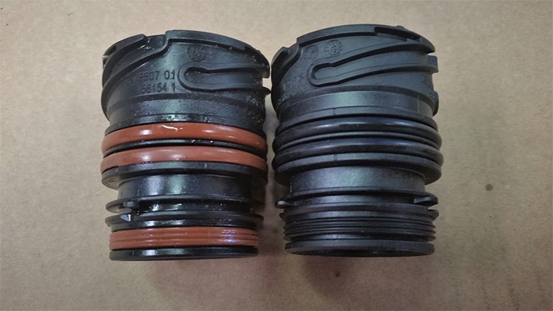
The o-rings on the old sleeve, shown on the left, are beginning to show wear. The o-rings on the new sleeve, shown on the right, are made from improved material.
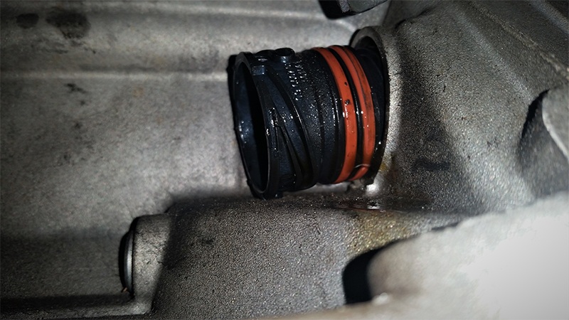
Note the indexing tab inside the sleeve. This must align with the notch in the Mechatronic unit.
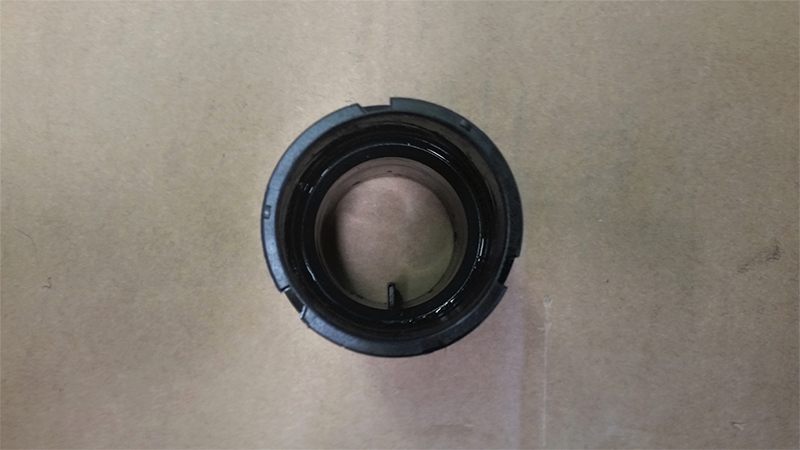
The notch is located in the 4 o’clock position inside the Mechatronic unit male connector.
Lubricate the o-rings on the sleeve with silicon grease to ease installation.
Insert the sleeve into the housing and rotate it until the indexing tab aligns with the notch. You can use a small mirror to verify that the two are aligned, before pressing in the sleeve.
Verify that the locking mechanism is in the downward position. Press the sleeve into the housing squarely with even pressure.

Press the sleeve into the housing using a suitable tool such as a pry bar. Be careful not to damage the sleeve. Wiggle the sleeve back and forth while you push the locking mechanism upward. Take your time and do not force anything. The locking mechanism will lock fully when everything is lined up.

Verify that the locking mechanism is locked in the full upward position.
Rotate the Mechatronic electrical connector locking ring clockwise until it clicks. The Mechatronic connector sleeve is correctly installed when there is a 3 mm gap between the locking ring and the transmission body. The easiest way to check this is to insert a 3mm Allen Wrench in the gap. It should fit snugly, as shown here. Failure to do this will result in transmission fault codes and a potential engine no start condition.

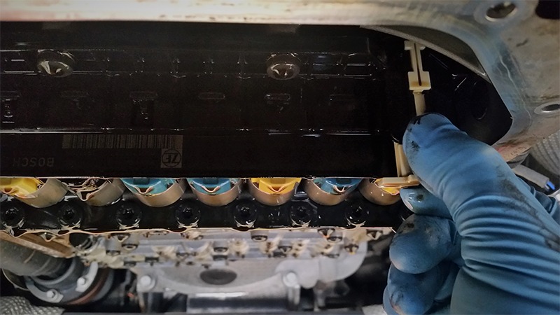
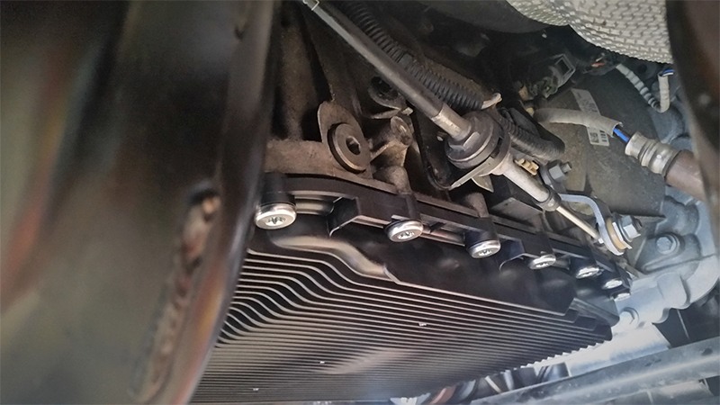
Clean the gasket mating surface. Ensure that it is smooth and free of any oil or debris.
Lubricate the oil filter tube o-ring with silicon grease or fresh transmission fluid.

Thread all the new oil pan bolts by hand prior to torquing them. Torque the bolts to 6 ft/lbs (8Nm)
Locate and remove the fill plug on the side of the transmission. Loosen the drain plug with an 8mm hex bit. The fill plug can be difficult to break loose, so take care not to damage the inside of the bolt head.
Fill the transmission until fluid emerges from the fill hole. Temporarily install the fill plug to prevent fluid loss. A hand pump and a transmission fill adapter make the job easier.
Start the engine and move the selector lever through the gear ranges several times. Monitor the transmission temperature with a factory-compatible scan tool. When the transmission fluid temperature reaches 30°C (86°F) the fluid level can be checked.
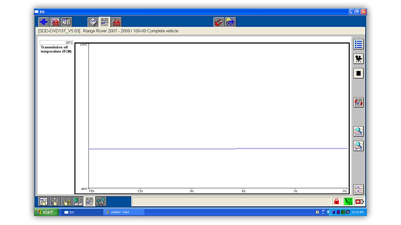
With the transmission fluid temperature at 30°C (86°F), fill the transmission until fluid emerges from the fill hole. The transmission fluid temperature must not exceed 50°C (122°F) during this procedure. Install the new fill plug with a new gasket and torque to 26 ft/lbs (35Nm)
DISCLAIMER
The information provided on this website is for informational purposes only and is subject to change without notice. While Newparts will attempt to update information it determines to be incorrect, Newparts does not warrant or represent the accuracy of the information found on this website. You shall have the sole responsibility for verifying its accuracy and shall bear the sole responsibility for using such information. Furthermore, if you use the information on this website to repair your vehicle or to replace parts on your vehicle, you represent and warrant that you have the skill and expertise necessary to perform such work. You further you agree and acknowledge that Newparts shall not be reasonable or liable for any damage to your vehicle or other property nor shall Newparts be liable to you for any injury or death resulting from your performance of any work on your vehicle.